
LED는 정방향전류($V_F$)를 조절함으로써 그 밝기를 조절할 수 있습니다. 정방향전류를 조절하는 방법은 옴의 법칙에 따라서 전압을 조절하거나 전류 제한을 위한 저항을 조절하면 되겠죠. 예전 글에서 가변 저항을 사용하여 LED의 밝기를 조절해 본 적이 있습니다.
그런데, 이것을 컴퓨터로 조절을 해 보려면 어떻게 해야 하죠? 라즈베리 파이에서 GPIO를 제어해 본 적이 있지만, 라즈베리 파이와 같은 미니 컴퓨터든 단일칩 마이크로 컨트롤러든 GPIO는 켜짐과 꺼짐, 2가지의 전압 밖에 출력을 할 수가 없는데요. 더욱이 컴퓨터로 저항(resistance)을 직접 조절할 수는 없습니다.
이런 경우에는 눈에 보이지 않을 만큼 빠르게 LED를 껐다 켰다를 반복하되 밝게 켜고 싶을 때에는 켜는 시간을 길게, 어둡게 하고 싶을 때에는 켜는 시간을 짧게 하는 방법을 사용합니다. 켜는 시간이 길어지면 그만큼 밝게 보이는 것이죠. 이렇게 표현하는 것을 PWM(Pulse Width Modulation)이라고 합니다.
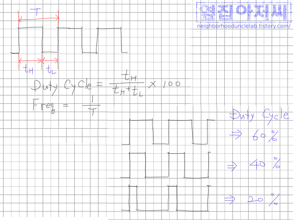
위의 그림에서, 하나의 주기 $T=t_H+t_L$로 신호가 HIGH인 시간과 LOW인 시간의 합이죠. 이 신호가 반복이 되는데, 이때 반복되는 주파수 $f=\frac{1}{T}$이 됩니다. 전체 한 주기 중에서 HIGH인 신호가 차지하는 비율을 Duty Cycle이라고 부릅니다. 오른쪽 아래에 있는 3개의 파형은 모두 주기는 동일하지만, Duty Cycle이 다른데요, 한 주기에서 HIGH인 주기가 차지하는 비율에 따라 그림에 나와 있는 것처럼 60%, 40%, 20% 등으로 나타나는 것입니다. LED가 신호가 HIGH인 동안에 켜지게 회로를 꾸몄다면 Duty Cycle이 높을수록 LED는 더 오래 켜질 것이고, 꺼졌다 켜지는 것이 눈으로 못 느낄 정도로 빠르게 반복된다면 더 밝게 느껴질 것입니다. 물론 신호가 LOW인 동안에 켜지도록 회로를 꾸몄다면 Duty Cycle이 낮을수록 더 밝겠지요.
그러면 실험을 통해서 확인을 해 볼까요? GPIO로 직접 전원을 공급하지 않고, MOSFET을 스위치로 사용하여 별도 전원으로 LED를 켜도록 하겠습니다. 다음에 나오는 회로도처럼 꾸며 보지요. 역시 라즈베리 파이에 연결할 것이구요, 라즈베리 파이의 GPIO 이름과 40핀 헤더에서 핀 번호를 함께 적어 놓았습니다.
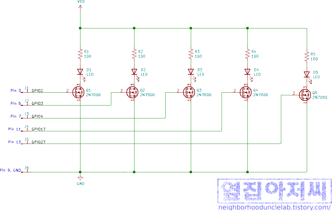

LED를 모두 켜면 40~50mA 정도 될 텐데, 라즈베리 파이가 이 정도 전류를 함께 공급 못 해 주지는 않겠지만, 우리가 꼭 LED만 사용하라는 법이 없으니, VDD는 외부에서 한 번 써 보려고요.
주의할 점은 전원을 외부에서 주더라도 라즈베리 파이와 전원, 그리고 꾸민 회로의 GND는 모두 함께 연결이 되어야 합니다. 기준점은 모두 동일해야 하니까요. GND가 함께 연결되어야 회로가 모두 동일한 기준점을 가지게 됩니다. 다시 말하면, 빵판의 GND는 전원 공급 장치의 GND와도 연결하고, 이것은 또 라즈베리 파이의 GND, 여기서는 40핀 헤더의 9번 핀과도 함께 엮어 주어야 한다는 것입니다. 만약 이 모든 GND를 연결하지 않으면 각자 자기 세상에서 놀기 때문에 서로 신호가 맞지 않습니다.
라즈베리 파이에서 다음을 실행시켜 볼까요? Python의 Interactive Mode에서 한 라인씩 차례대로 실행시켜도 되고, 파일 하나로 배치 실행하여도 됩니다.
import RPi.GPIO as GPIO
GPIO.setmode(GPIO.BCM)

GPIO.setup(2,GPIO.OUT)
GPIO.setup(3,GPIO.OUT)
GPIO.setup(4,GPIO.OUT)
GPIO.setup(17,GPIO.OUT)
GPIO.setup(27,GPIO.OUT)

p1=GPIO.PWM(2, 1000)
p2=GPIO.PWM(3, 1000)
p3=GPIO.PWM(4, 1000)
p4=GPIO.PWM(17, 1000)
p5=GPIO.PWM(27, 1000)

p1.start(100)
p2.start(60)
p3.start(30)
p4.start(15)
p5.start(7)
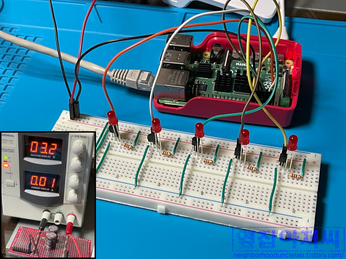
다음 사진처럼 보일 텐데요, 밝기 차이가 잘 보이는지 모르겠네요.
일부러 눈에 잘 띄게 하기 위해서 약 2배씩 차이를 두어 보았습니다. 왼쪽 LED부터 Duty Cycle 100%, 60%, 30%, 15%, 7%입니다. 밝기 차이가 느껴지나요?

RPi.GPIO 모듈은 라즈베리 파이에 기본적으로 설치가 되기 때문에 별도로 설치할 필요는 없습니다. 대신 사용하기 위해선 import를 해야죠. PWM 출력으로 GPIO를 사용하기 위해서는 먼저 OUT으로 설청을 하여야 합니다.
GPIO.setup(2,GPIO.OUT) # Ex) GPIO2를 출력으로 설정해당 GPIO를 사용하는 PWM Instance를 생성합니다.
p1=GPIO.PWM(2, 1000) # Ex) GPIO2를 사용하면서 주파수가 1000Hz, 즉 TH=TL=1msec인 PWM 인스턴스그리고, Duty Cycle을 지정하여 PWM 출력을 시작합니다.
p1.start(80) # Ex) p1 인스턴스를 사용하여 Duty Cycle 80%인 PWM 출력 시작
다음 명령어를 실행하면 하나씩 LED가 꺼질 것입니다.
p1.stop()
p2.stop()
p3.stop()
p4.stop()
p5.stop()
시작한 김에 재미있게 해 보죠. GPIO2에 연결되어 있는 LED를 Duty Cycle 0~100%까지 변화시키면서 밝기 변화를 보겠습니다.
다음 코드를 실행시켜 볼까요. 이미 앞서 설명한 것들이 있으니 코드 자체는 쉽게 이해가 될 것입니다.
import RPi.GPIO as GPIO
from time import sleep

GPIO.setmode(GPIO.BCM)
GPIO.setwarnings(False)
GPIO.setup(2, GPIO.OUT)

pwm = GPIO.PWM(2, 1000)

dc = 100 # Initial value of Duty Cycle
pwm.start(dc) # Start PWM
direction = -1 # Initial Direction: Decreasing

try:
    while(True): #Ininite Loop except for break by user
        dc = dc + direction # Update Duty Cycle
        pwm.ChangeDutyCycle(dc) # Apply change
        if(dc <= 0 and direction == -1): # If Duty Cycle was decreasing and now reach to 0
            direction = 1
        elif(dc >= 100 and direction == 1): # If Ducy Cycle was increasing and now reach to 100
            direction = -1
        sleep(0.01)

except KeyboardInterrupt:
    pwm.stop()

GPIO.output(2, GPIO.LOW)
다음 이미지처럼 나타난다면 제대로 된 것입니다.
결국 켰다가 껐다가 하는 비율을 조정해서 밝기를 조절하는 것인데, 뭐 거창하게 아날로그의 표현이라고 하느냐, 결국 LOW와 HIGH 레벨 밖에 없지 않으냐라고 하는 분이 계실지 모르겠습니다. 맞아요. 전압 레벨은 HIGH와 LOW만 존재합니다. 그럼 디지털만 존재하는 것인가요? 가만히 신호를 살펴보면 아날로그가 있습니다. 바로 Duty Cycle을 연속적인 값, 즉 아날로그(Analog)입니다. 전압 레벨은 2가지 밖에 나타낼 수가 없으니까 HIGH인 시간과 LOW인 시간의 비율을 사용하여 아날르그를 표현하는 것입니다. 많은 반도체 소자들이 아날로그 값을 표현하기 위하여 PWM을 많이 사용을 합니다.
PWM은 적절한 회로만 추가하면 아날로그 전압 레벨로도 변환할 수가 있습니다. 실제 회로에서 오실로스코프를 사용해서 파형을 살펴 보면 좋겠지만, 오실로스코프가 없으니 시뮬레이션으로 살펴 보겠습니다.
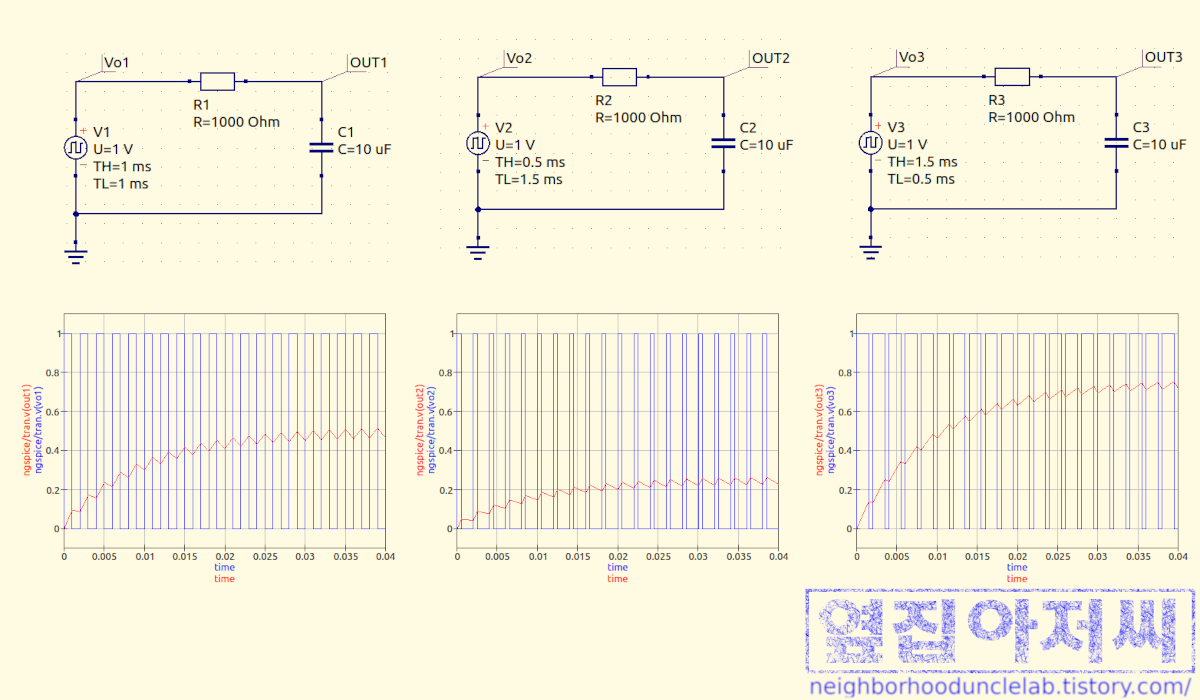
위의 그림에서 각각의 시뮬레이션 모델을 통해서 얻은 결과를 아래에 짝지어 그려 놓았습니다. QUCS라는 프로그램을 사용하여 시뮬레이션하였습니다.
각각의 시뮬레이션 회로에서 $V1$, $V2$, $V3$ 전압원은 PWM 출력입니다. 모두 공통적으로 $T_H+T_L=2 ms$로 500㎐의 PWM입니다. 각 전압원에 다른 점은, $\frac{T_H}{T_H+T_L}$, 즉 Duty Cycle이 각각 $\frac{1ms}{2ms}=50\%$, $\frac{0.5ms}{2ms}=25\%$, $\frac{1.5ms}{2ms}=75\%$라는 것입니다. 또, 모든 회로의 PWM 출력에는 직렬 연결된 저항(resistor)과 여기에 병렬 연결된 커패시터(capacitor)가 있으며, 여기에서 OUT1, OUT2, OUT3의 출력을 얻습니다.
각 그래프에서 파란색은 각 전압원의 PWM 출력이고, 빨간색은 각 회로에서의 출력입니다.
연결된 저항과 커패시터가 어떤 동작을 하는지는 이야기한 적이 없었네요. 다음 기회에 자세히 이야기해 보도록 하구요, 저역통과필터 또는 로우패스필터(Low Pass Filter)라고 하는데, 어쨌든 각 회로의 출력은 조금씩 다른 것이 보이죠? 각 PWM 출력의 Duty Cycle에 비례해서 전압 레벨이 변환된 것을 볼 수 있습니다.
PWM이 아날로그를 표현하고 있다는 것을 보여 주는 의미에서 이야기를 꺼내 보았습니다.
LED의 밝기를 마음대로 조절할 수가 있으니 또 하나 재미있는 것 해 보면서 이번 글도 마무리하려 합니다.
이번에는 지난번에 만들었던 LED Class를 상속하여 계속해 보았습니다. 상속을 한 것이니 지난번에 했던 코드도 필요하겠죠.
Github repository를 그대로 clone 하면 그대로 동작할 것입니다만, 지난번 코드를 같은 디렉터리에 넣는다면 import 할 때 주의하세요. 그냥 생각나는 대로 하다 보니 코드는 좀 지저분하게 된 것 같습니다만, 재미는 있을 것입니다.
# This is to use a previous project as a module
# With this, we can import a project in the parent directory as a module
import sys
sys.path.append('..')

# Refer to https://sourceforge.net/p/raspberry-gpio-python/wiki/Home/
# for RPi_GPIO module
import RPi.GPIO as GPIO

# Import all classes and constants from the previous project
from led_control.led_toggle import *

DEFAULT_FREQ = 1000

class DIMMER(LED):
    '''
    Class for LED Dimming control
    Inherits class LED
    '''
    def __init__(self, gpio, polarity=POLARITY.ACTIVE_HIGH):
        '''
        Initialize self. Specify gpio and polarity.
        The polarity is ACTIVE_HIGH by default.
        '''
        super().__init__(gpio, polarity)
        self.is_dimming_running = False
        self.dim = GPIO.PWM(gpio, DEFAULT_FREQ)
        self.level = 0

    def dimming(self, duty_cycle):
        '''
        Dimming the LED per duty_cycle
        0 <= duty_cycle <= 100
        '''
        if duty_cycle > 100:
            duty_cycle = 100
        if duty_cycle < 0:
            duty_cycle = 0
        # if (self.is_dimming_running):
        #     self.dim.ChangeDutyCycle(duty_cycle)
        #     if duty_cycle == 0:
        #         self.is_dimming_running = False
        #         self.dim.stop()
        # else:
        #     self.dim.start(duty_cycle)
        #     self.is_dimming_running = True
        self.level = duty_cycle
        if self.level == 0:
            self.dim.stop()
        else:
            self.dim.start(self.level)

    def get_current_level(self):
        '''
        Return current dimming level
        '''

        return self.level

# main
if __name__ == '__main__':
    # import time module for sleep to delay
    # Used only here so imported in this block
    import time
    import pdb

    GPIO.setmode(GPIO.BCM) # Specify the GPIO numbering mode.
    GPIO.setwarnings(False)

    # Functions for demo
    def demo0(led_array):
        '''
        Run this demo for about 5 sec
        On/Off all LEDs
        '''
        start_time = time.time_ns()
        current_time = time.time_ns()
        while((current_time-start_time)<5000000000):
            # Turn on all LEDs
            for led in led_array:
                led.on()
            # Delay to get LEDs on
            time.sleep(0.5)

            # Turn off all LEDs
            for led in led_array:
                led.off()
            # Delay to get LEDs off
            time.sleep(0.5)
            current_time = time.time_ns()

    def demo1(led_array):
        '''
        Run this demo for about 5 sec
        Dim up and down all LEDs
        '''
        start_time = time.time_ns()
        current_time = time.time_ns()
        current_dim_level = 100 # Initial Level
        current_dim_direct = -1 # Initial Direction of Dimming
        while((current_time-start_time)<5000000000):
            # Update the level of all LEDs
            for led in led_array:
                led.dimming(current_dim_level)

            # Calculate next level
            current_dim_level = current_dim_level + current_dim_direct
            if current_dim_level < 0 and current_dim_direct == -1:
                # The level was decreasing and we reach to 0
                current_dim_level = 0
                current_dim_direct = 1
            if current_dim_level > 100 and current_dim_direct == 1:
                # The level was incrasing and we reach to 100
                current_dim_level = 100
                current_dim_direct = -1

            # Delay
            time.sleep(0.005)
            current_time = time.time_ns()

        # Stop PWM
        for led in led_array:
            led.dimming(0)

    def demo2(led_array):
        '''
        Run this demo for about 10 sec
        Dimming LEDs sequentially
        '''

        decay = 20
        start_time = time.time_ns()
        current_time = time.time_ns()

        # Initialize dimming level of each LEDs for demo
        dim_levels = dict()
        for led in led_array:
            dim_levels[led] = 100

        while((current_time-start_time)<10000000000):
            for led in led_array:
                # Dimming each LED
                # 0 if the calculated level < 0, 100 if the calculated level > 100
                led.dimming(0 if dim_levels[led]<0 else 100 if dim_levels[led]>100 else dim_levels[led])

            for led in led_array:
                # Decay the level of the first LED
                if led_array.index(led) == 0:
                    dim_levels[led] = dim_levels[led]- decay
                else:
                    # Decay the level of remaining LEDs depending on the previous LED
                    if dim_levels[led_array[led_array.index(led)-1]] <= (100-2*decay) :
                        dim_levels[led] = dim_levels[led] - decay
                if led_array.index(led) == len(led_array)-1 and dim_levels[led] < 0:
                    # We've done a cycle
                    for led in led_array: # Re-init the levels
                        dim_levels[led] = 100
                    time.sleep(0.5) # Delay
            time.sleep(0.1)
            current_time = time.time_ns()

        # Stop PWM
        for led in led_array:
            led.dimming(0)

    # Main routine starts here
    gpios = (2,3,4,17,27) # GPIOs to be configured
    led_array = list() # List for LEDs in the array

    # Initialize the array of LEDs with the class instance
    for gpio in gpios:
        led_array.append(DIMMER(gpio))

    try:
        while(True):
            demo0(led_array)
            time.sleep(1)
            demo1(led_array)
            time.sleep(1)
            demo2(led_array)
    except KeyboardInterrupt: # Ctrl+C will bering us here.
        GPIO.cleanup()
        exit(0)
다음 동영상처럼 동작할 거예요.
코드는 Github를 통하여 공유해 두도록 하겠습니다.
https://github.com/sangyoungn/play_with_RPi/PWM
GitHub - sangyoungn/play_with_RPi: Example Codes for Raspberry Pi
Example Codes for Raspberry Pi. Contribute to sangyoungn/play_with_RPi development by creating an account on GitHub.
github.com
'전자공학을 즐겁게 > 누구나 취미전자공학' 카테고리의 다른 글
| 커패시턴스(Capacitance)로 만드는 지연(delay) (2) | 2023.02.05 |
|---|---|
| 커패시터(Capacitor)에 대하여 (2) | 2023.01.15 |
| 스위치로서의 MOSFET (2) | 2022.12.20 |
| FPL 모양 LED 조명 분해해 보기 (0) | 2022.12.05 |
| 라즈베리 파이(Raspberry Pi)에서 RPi.GPIO Python module을 사용한 GPIO 출력 제어, 그리고 Drive Strength에 대하여 (0) | 2022.10.29 |


